Electronics
Showing 49–64 of 339 results

Class “A” Amplifier
Class “A” Amplifier Class A Amplifiers are the most common type of amplifier class due mainly to their simple design. The class A amplifier has the highest linearity over the other amplifier classes and as such operates in the linear portion of the characteristics curve. Generally class A amplifiers use the same single transistor (Bipolar, FET, … Continue reading “Class “A” Amplifier”
Class “AB” Amplifier
Class “AB” Amplifier Class AB Amplifier is a combination of the “Class A” and the “Class B” type amplifiers we have looked at above. The AB classification of amplifier is currently one of the most common used types of audio power amplifier design. The class AB amplifier is a variation of a class B amplifier as … Continue reading “Class “AB” Amplifier”
Class “B” Amplifier
Class “B” Amplifier Class B amplifiers were invented as a solution to the efficiency and heating problems associated with the previous class A amplifier. The basic class B amplifier uses two complimentary transistors either bipolar of FET for each half of the waveform with its output stage configured in a “push-pull” type arrangement, so that each … Continue reading “Class “B” Amplifier”
Class “C” Amplifier
Class “C” Amplifier The Class C Amplifier design has the greatest efficiency but the poorest linearity of the classes of amplifiers mentioned here. The previous classes, A, B and AB are considered linear amplifiers, as the output signals amplitude and phase are linearly related to the input signals amplitude and phase. class C amplifier is heavily biased so that the output … Continue reading “Class “C” Amplifier”
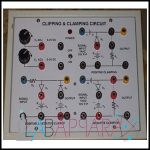
Clipping & Clamping Circuit Apparatus
Clipping & Clamping Circuit Apparatus – Electronics Laboratory Equipment With the help of our experienced professionals, we have been able to offer Clipping & Clamping Circuit Apparatus. These devices are based on modern technology and are provided with superior features. Our professionals make sure that these are rigorously tested for quality to ensure optimum safety … Continue reading “Clipping & Clamping Circuit Apparatus”
Colpitt Oscillator
Colpitt Oscillator Features : Circuit Printed on Bakelite sheet Tank Circuit with 2 Capacitors & 1 Inductance Switch : Selects different Values of Capacitor. Output Connected to CRO
Common Base Transistor Amplifier
Common Base Transistor Amplifier Features: Instrument comprises of the following DC Regulated Power Supply Circuit diagram printed on the front panel. Components mounted on the front panel. One ON/OFF Switch with jewel light is provided on the front panel. Made of Heavy duty metal box construction Accessories Supplied: Required number of Patch Chords Instruction Manual
Common Collector (Emitter Follower) Transistor Amplifier
Common Collector (Emitter Follower) Transistor Amplifier Features:- Instrument comprises of DC Regulated Power Supply, Circuit diagram is printed, components mounted on the front panel.
Common Emitter Transistor Amplifier
Common Emitter Transistor Amplifier Features : Instrument comprises of DC Regulated Power Supply, Circuit diagram is printed, components mounted on the front panel.
Compensators (Analog Phase Meter)
Compensators (Analog Phase Meter) The instrument consists of two – round scales. One with index and the other with vernier. The first scale (index scale) is for tuning the analyser into the azimuth. The Second scale (Vernier Scale) is for measuring the degree of orientation of a wedge box. The Wedge Box contains two wedges … Continue reading “Compensators (Analog Phase Meter)”
Complementary Symmetry Amplifier
Complementary Symmetry Amplifier Features : Instrument comprises of fixed output DC Regulated Power Supply of 12V, Circuit diagram is printed, Components mounted behind the front panel & connections of important points brought out at 4 mm Sockets.
Constant “K” Filters
Constant “K” Filters Specification : Constant k filters, also k-type filters, are a type of electronic filter designed using the image method. They are the original and simplest filters produced by this methodology and consist of a ladder network of identical sections of passive components.
Conversion Of Galvanometer Into Ammeter
Conversion Of Galvanometer Into Ammeter Features : Instrument comprises of DC Regulated Power Supply 0-5VDC/150mA, two round meters (One milliammeter & One Galvanometer), Three set of Shunts resistance mounted behind the panel, connections of supplies, Meters & Shunts brought out at 4mm Sockets.
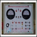
Conversion of galvanometer into voltmeter
Conversion of galvanometer into voltmeter – Electronics Laboratory Equipment To convert a voltage to a current, use ohm’s law to select the resistor. Subtract the resistance of the galvanometer if it is known. If the galvanometer is 100 μA full scale and you want to display 10 V full scale then you will need a … Continue reading “Conversion of galvanometer into voltmeter”
CRO 10MHz, Single Channel
CRO 10MHz, Single Channel Specifications: Bandwidth: 10 MHz ANALOG; Channels: 1; Input impedance: 1 MOHM +/-3%; Input capacitance: 30 pF +/- 5 pF; Rise time: < 35ns; Max input voltage: 400V (DC + AC PEAK); Sensitivity: 0.2V/DIV-0.5V/DIV; Lightweight with low power consumption TV synchronizing, X-Y operating Supplied with 1 (X1, X10) probe and manual High performance … Continue reading “CRO 10MHz, Single Channel”
CRO 20MHz, Dual Channel Dual Trace
CRO 20MHz, Dual Channel Dual Trace CRO 20MHz, Dual Channel, 2 Trace. Cathode Ray Oscilloscopes :- a) Screen: Diameter 5”, green phosphor b) Vertical Frequency Response: 1) + 3db 4 Hz 1.2 MHz. 2) + 6db 3 Hz 2 MHz. c) Sensitivity : 0.09 RMS volts per inch at 1 KHz d) Input Impendence at … Continue reading “CRO 20MHz, Dual Channel Dual Trace”